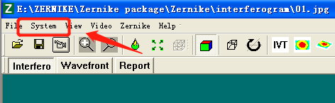
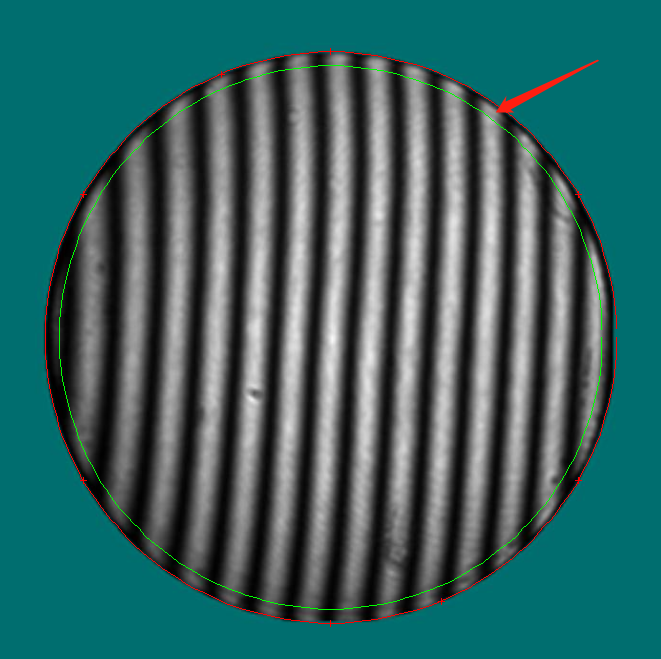
We will use the follow picture, which was taken from the interferometer directly or captured the picture with JPG or BMP format.
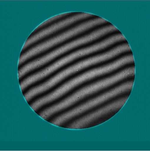
Import it to the software with open button.
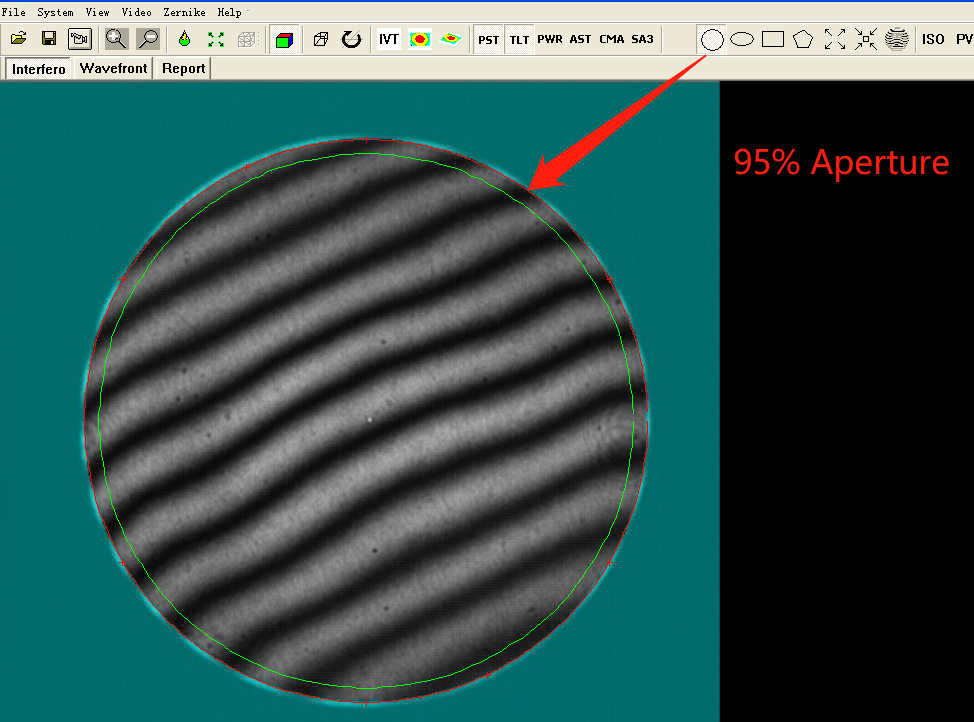
The default clear aperture is 95%, if you want to change it please read the follow link
http://www.soubey.com/en/technology/309-how-to-set-the-parameters-in-zernike.html
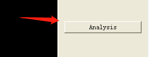
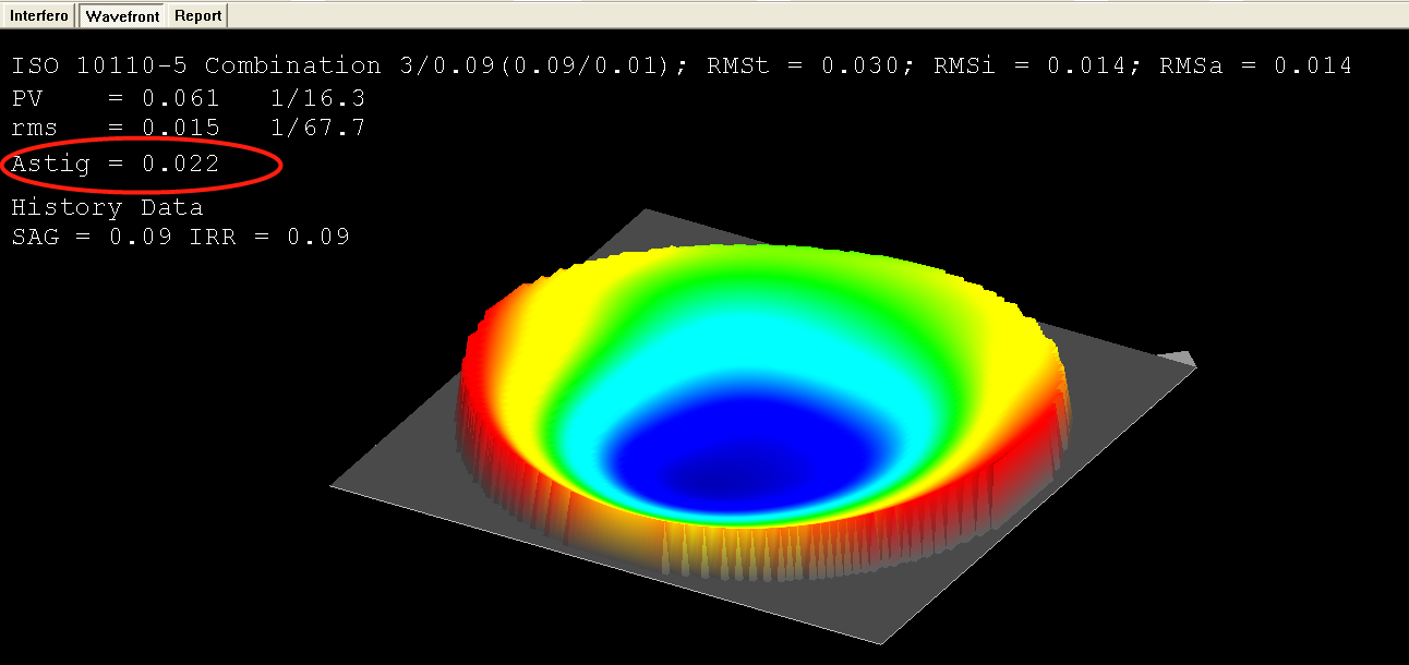
Click the analysis button
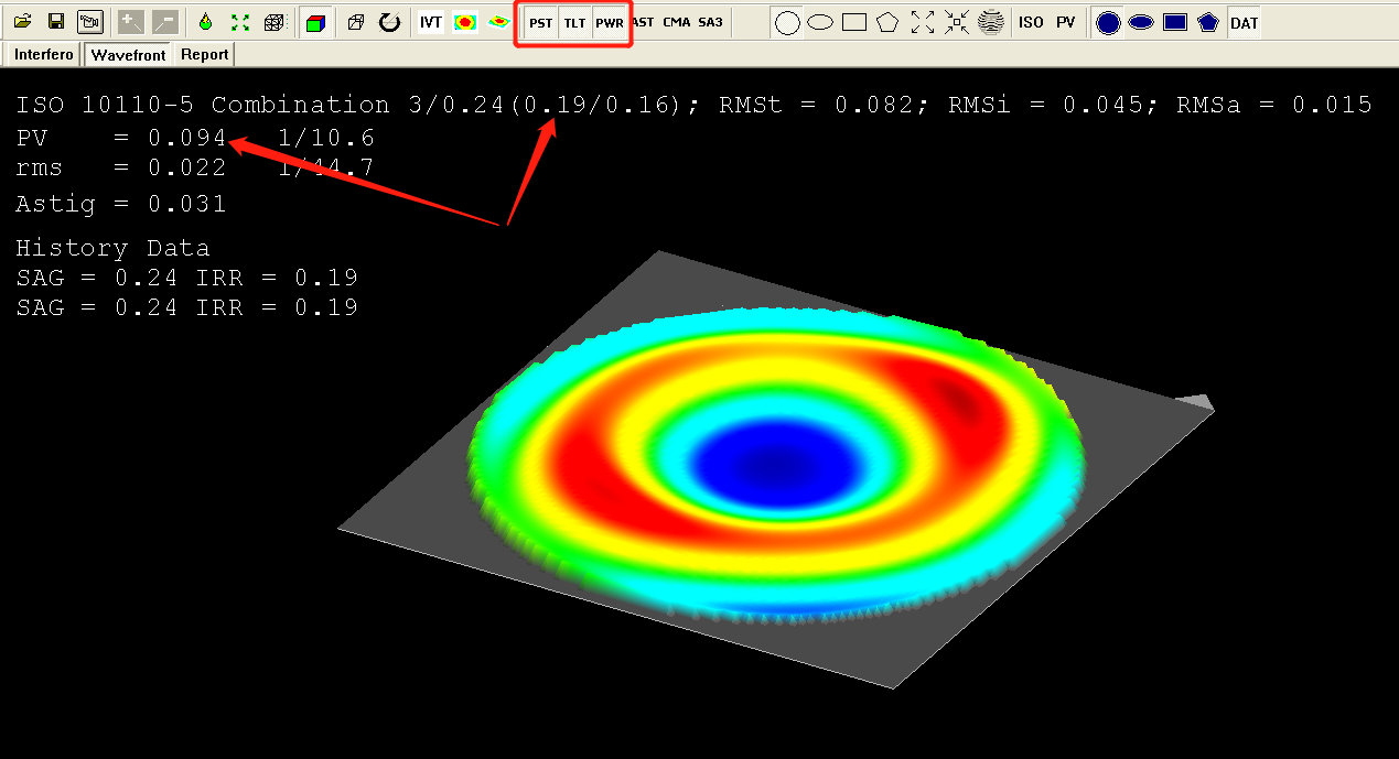
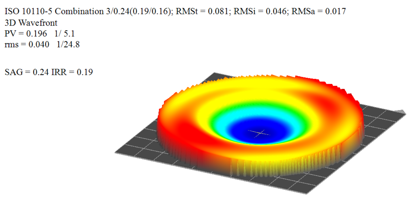
The page tab will change to Wavefront and you can find the analysis result here
ISO result: 3/ 0.24 / (0.19 / 0.16) means that the power N is 0.24 and the delta N is 0.19.?
PV = 0.196? means the peak to valley is 0.196 wave.
rms = 0.041 means?Root Mean Square.
We have added the Astig display here, shows that the Astigmatism Item contribute 0.031 wave.
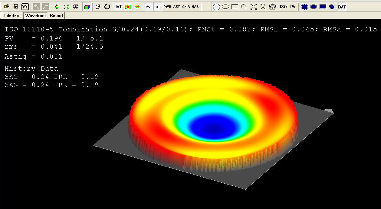
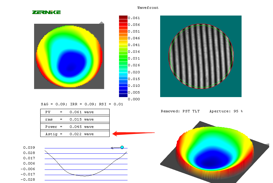
If you removed the power item from the button, the PV should be 1/2 of the delta N, you should do this for sphere measurement.
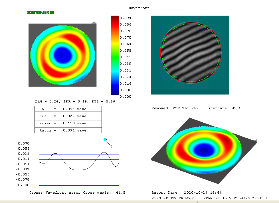
You will get all the information from the report, you can print it or save it as JPG format with save button.
?
?
]]>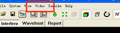
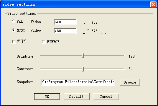
The video dialog?
if your interferometer is ZYGO or Fuji, you should use the NTSC mode.
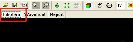
Click the Interfero tab?to change the software to interferogram interface
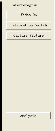
On the right side, you will find the video operation buttons
[video on]: Turn on the video device.
[Calibration Switch]: Change the ports of the video device AV1 to AV2 or AV2 to AV1. SHORT KEY [TAB]
[Capture Picture]: Get the video to picture used to analysis. SHORT KEY [SPACE]
[Analysis]: Calculate the finger to wavefront map to analysis the result.? SHORT KEY [ENTER]
Exchange the video from right top position to fit the screen. SHORT KEY [F4]
Resize the selection picture. SHORT KEY [F3]
[open] [save] [video] [zoom big] [zoom samll]
VIEWER BUTTON

[backgroud] [zoom fit] [grid show] [color show] [ortho] [rotation]
VIEWER BUTTON 2
[invert view] [front view] [oblique view]
ZERNIKE BUTTON

[piston] [tilt] [power] [astigmatism] [coma] [spherical]
RANGE SELECTION BUTTON

[circle] [ellipse] [rectangle] [polygon]
PICTURE RESIZE BUTTON
[resize big] [resize small] [restore picture]
RESULT BUTTON

[iso result] [pv result]
MASK SHAPE BUTTON
[circle] [ellipse] [rectangle] [polygon]
HISTORY BUTTON

[history data]
]]>
The setting dialog will be opened.
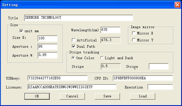
Input the group or company name in the title
If your interferometer is working with He-Ne laser,? set the wavelength to 632.8nm
For?Fizeau interferometer, please keep the Stripe value to 0.5
If the clear aperture is 95%, you can type 0.95 to the Aperture % directly.
The result display depends on the ISO item and it will be showing with ISO togather.

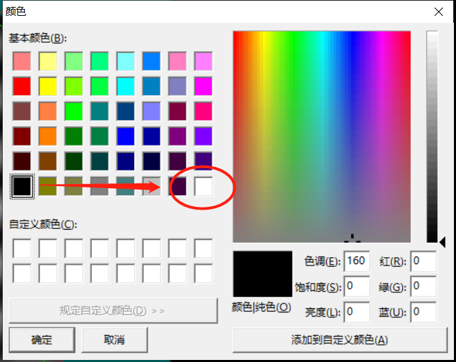
The new background will be changed, and the lastest version of the program can remeber it when you open it next time.?

Select the color you want to use.
?

![]()
?Select the range with clockwise direction

The interferometer is a very sophisticated testing instrument. It should be understood that the basic maintenance and maintenance in daily use should ensure the measurement accuracy of the interferometer as much as possible and prolong the service life of the interferometer.
Precautions
1. The instrument should be placed in a dry, clean and vibration-free environment.
2. When moving the instrument, in order to prevent the deformation of the guide rail, the base should be supported and then moved.
3. When the optical parts of the instrument are not in use, they should be stored in clean and dry containers to prevent mold.
?4, try not to wipe the mirror, beam splitter, etc. of the instrument, if you must wipe, you should carefully wipe, use scientific methods to clean.
5. Transmission components such as guide rails, lead rods, nuts and shaft holes should be well lubricated. Therefore, use precision instrument oil lubrication if necessary.
6. When using, avoid strong rotation, hard pull, etc., and adjust the parts reasonably and properly.
7, to avoid scratching or corroding the rail surface screw, to keep it without losing oil.
?
Routine maintenance
1. The instrument should be properly placed in a dry, clean room to prevent vibration. When the instrument is moved, the base should be supported to prevent deformation of the guide rail.
2. When the optical parts are not in use, they should be stored in a clean drying basin to prevent mold. Mirrors and beamsplitters are generally not allowed to be wiped. When necessary, the dust must be carefully removed with a spare brush, and then wiped with a mixture of alcohol and ether with a degreased cotton ball.
3. The transmission components should have good lubrication. In particular, the guide rail, screw, nut and shaft hole parts are lubricated with T5 precision instrument oil.
4. When using, the force of each adjustment part should be appropriate, not strong rotation or hard pull.
5. The screw on the surface of the guide rail should be protected from scratches and rust. After use, it will remain oil-free.
6. The screws on the precisely adjusted instrument parts are painted with red paint and should not be rotated.
]]>?
The first is the Newton Interferometer Newton Interferometer
The Quasimonochromatic point source on the left is a point source with a nearly single wavelength. Quasimonochromatic means single wavelength, and point source is point source.
After the point source passes through the lens and becomes parallel light, it hits the lower elliptical object to be tested. The object to be tested may be an object such as a lens, and the plane under the object to be tested is a reference plane, which is usually used as a reference surface. The flatness, that is, the Surface irregularity, must be 1/10λ or more. The larger the denominator, the better the flatness.
?
The second is the Michelson Interferometer.
When the Michelson interferometer is compared with the Newtonian interferometer, it will be found that it is not a point source, the light source is somewhat scattered, and the light passes through the middle beam splitter O after passing through the first lens, so that part of the light is reflected to the reflection. The mirror M2 is reflected back to the beam splitter O, and a part of the light penetrates the compensator C. After reaching the mirror M1, it is reflected back to the beam splitter O to synthesize the same light, and the result is hit on the D (Detector), so we You can see a circle of stripes on the Detector, which is the interferogram A. So the Michelson interferometer is usually used to measure the change of the distance. When we want to measure the distance, we only need to measure the original interference fringe A. Then, the mirror M2 is moved backward, the interference fringe B is measured, and then the distance can be calculated from the change of the stripe A~B.
?
The third is the Fizeau Interferometer
The Fizeau interferometer is the most common interferometer at present. It is also the simplest architecture and the most convenient one. The laser beacon laser source is the upper left. The laser source is a very good single-wavelength source. After several procedures in the middle. When passing through the Reference flat reference surface, part of the light is reflected, and part of the light penetrates into the flat under fest surface to be reflected and then reflected back. Therefore, the result we see is the difference between the reference surface and the surface to be tested. When the reference planes are different, the measured surface stripe to be tested will be different. The disadvantages of this interferometer are: It is easily affected by external forces such as wind direction, vibration, and air changes, and must be placed on the earthquake-proof table in a closed room. In order to clearly see the interference fringes, it is also known as the non-co-path interferometer.
?
The fourth is the Mach-Zehnder interferometer
The extended source at the lower left is an extended source similar to the Michelson interferometer. The light source is split into two passes after the first Beam-splitter, each passing through a Mirror mirror and then synthesized by a second Beam-splitter. After a light, the result is hit on the Detector. Because the middle is divided into two light sources, the space and distance can be adjusted greatly, so it is more suitable for measuring large or penetrating objects, for example: Can be used to measure large areas of glass. Place the object under test between the first Beam-splitter and Mirror mirror on the path, we can see the difference between path A, path B and the object to be tested. This is also a non-co-path interferometer. Its disadvantages are: It is easily affected by external forces such as air changes. The advantages are: It can measure objects with large volume or area.
?
?
The fifth is the Twyman-Green interferometer
The Twyman-Green interferometer is similar to the Michelson interferometer. When a light source comes in, after the BEAM EXPANDER makes the light source larger, it is divided into two lights by the middle BEAMSPLITTER, and then reflected back to the detector. Interferometers have different application ranges, directions and restrictions.
]]>? ? There are two types of interference fringes: the first one is an equal thickness interference fringe, and the light and dark stripes in the equal thickness interference fringes are equally spaced, and each adjacent strip represents the same thickness interval.
Assume that the horizontal line is the standard surface, and the oblique line is a surface to be measured with a fixed slope. When the light hits, the refraction phenomenon will occur. We make a dotted line parallel to the standard surface at the first injection point, and the surface to be tested will be Light a is reflected back, and light b is reflected back on the standard surface. It can be seen from the figure that the paths through which light rays a and b pass are different, and when the optical path difference is exactly an integer multiple of the wavelength, it can be seen. Interference fringes to the same interval
? ? The second is an isosceles interference fringe, which is an interference fringe formed by rays of the same angle. P1 has an interference fringe whose source is caused by four solid lines, and the four solid pairs The surface of the object is caused by the same angle of light, because the object is circular, so it will cause symmetrical effect. The four dotted lines are caused by light of another angle, and then P2 is generated. An interference fringe of a point. Therefore, the interference fringes formed by the same angle of light are called equal-inclination interference fringes, but in practical applications, equal-thickness interference fringes and isosceles interference fringes may occur simultaneously.
Application: Surface flatness
? ? If we want to understand the flatness of the surface of the object from the interferogram, we can draw a crosshair centered on the interferogram, counting the number of stripes in the X direction and the Y direction from the center point. There are several stripes, which is the most commonly used in optical factories. When we ask Master to grind a lens, we can tell us the need for surface flatness, the tolerance of the error range in the X and Y directions. how many.
? Suppose that there is 1 stripe in the X direction and 3 strips in the Y direction. That is to say, the component to be tested changes in the X direction and the Y direction. The degree of change is defined as the surface. The uniformity of the surface irregularity is defined as: POWER, which is 3 in the Y direction, and irregularity is the difference between the X direction and the Y direction, that is, 2, so we can use the interference fringe from the above figure. Know that the power of the object to be tested is 3, the irreverity is 2, what exactly is POWER, what is irreregularity?
Suppose that the component we are looking at is the lens of the glasses. When viewed from the side, the lens will focus when there is light, and the degree of focusing will be different for different bending amounts. We call it magnification, and the degree of curvature of the surface is defined. For POWER. The degree of bending in the X and Y directions on the lens may be different, that is to say, POWER is not the same, we call it Surface irregularity,
Now that we know that the interferogram fringe is represented as 3/2, what is the number represented? His unit is the wavelength, generally 632.8nm wavelength, 3/2 3 means 3 wavelengths, 2 means 2 The wavelength is usually expressed in wavelengths in the calculation of optical components.
Note: We use wavelengths as the evaluation unit in interferometer measurements, so we also need to pay attention to the wavelength of the interferometer used. Suppose the same lens, the A manufacturer uses the interferometer with λ=500, the interpretation data is 3/2, the B manufacturer uses the interferometer with λ=600, and the interpretation data is also 3/2, then the A manufacturer using the 500λ interferometer The data must be better, because the shorter the wavelength, the smaller the conversion to data, so in addition to interpreting the data of the interferogram, it is also necessary to pay attention to whether the wavelength used for the interference matches the requirements to get the most correct. result.
Example 1: What can we read from POWER and Irregularity from Figure A?
After adding the cross coordinate, there are 2.5 stripes in the X direction and 1.5 stripes in the Y direction, so the maximum bending amount of this lens is 2.5, and the difference between X and Y is 1, but the result of this interferogram is not 2.5/1
When the X direction is the same as the bending direction of the surface to be tested in the Y direction, the irregularity is subtracted by 2, but when the bending direction of the X direction and the Y direction is different, the irregularity is added.
When the X direction is the same as the bending direction of the surface to be tested in the Y direction, POWER takes the maximum value, but when the X direction and the Y direction are different in the bending direction of the surface to be tested, the POWER is subtracted.
Therefore, the irregularity calculated from this figure is 1.5+2.5=4, and the X direction and the Y direction can be regarded as the same face, so the POWER is 2.5-1.5=1. Therefore, we must first know what object is measured, otherwise The data obtained may also be wrong.
Several common interference fringes:
It should be noted that the interference fringes in these figures are caused by the comparison of the object to be tested and a standard plane. Once the stripe is changed, the resulting strips will all change, and the corresponding conditions will be completely different.
The Without tilt on the left side is: When there is no tilt effect coming in, the stripe changes produced by different surfaces to be tested
The On tilt on the right side is: When the tilt effect comes in, the fringe changes produced by different surfaces to be tested
1 or 2 when the surface to be tested is flat, Without tilt will not see the stripes
When the surface to be tested is curved surface 3, Without tilt will present concentric circles with dense edges and unequal spacing.
When the surface to be tested is spherical 4, Without tilt will present concentric circles with equal spacing.
Assuming that the standard surface is a plane, the shape of the object to be tested may be hyperbolic or ellipsoid, so the thickness changes more severely, and the object to be tested of 4 may be spherical or nearly spherical.
Therefore, when doing interferometer measurement, when you want to judge the shape of the interference fringe, you must first understand the shape of the object to be measured, or judge the shape of the object by the shape of the interference fringe.
? ? Because the interference fringes will vary with the reference plane, so when I want to know the shape of the surface to be tested, I must first know what the shape of the standard surface is. Now let's take the same shape of the object to be tested - convex lens as an example.
? ? When the object to be tested is a spherical surface and the reference surface is a standard plane, the interference fringes may be a concentric circle distribution. However, if the reference surface is changed to the spherical surface of the standard curvature, the interference fringes may become a straight line distribution. The reason why the side has different interference fringe distribution is that the interference fringe sees the difference between the side to be referenced and the reference surface. Therefore, if you want to judge which interference fringe the object to be tested is a spherical surface, you must first understand. What is the reference referenced during the measurement? The shape of the surface to be tested can be judged correctly by the interference fringes.
]]>